

September 2003.
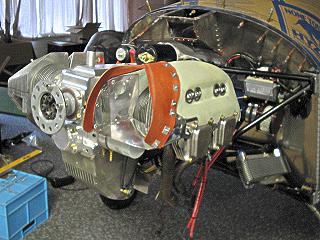
The cowling is the last major job requiring fabrication and fitting of parts. I had purchased the cowling ready-made from Sonex, so though that it would go together quickly. Another misconception in a long line of wrong thoughts. I did a lot of the work on the cowling in September but it dragged on and much of the finishing work was done in December.

Fitting of the cowling starts by making a wooden hub screwed to the engine prop hub. The preformed blanks are then fitted and trimmed as necessary.

Here you can see here the hinges being fitted to join the cowling halves. Like other parts of the design, the hinge pins are removed to separate the pieces. They don’t actually hinge. You can just see the line of rivets attaching the hinge of the rear side of the cowling.

The Jabiru engine comes with fibreglass air scoops to direct cooling air over and through the cylinder head fins. The Sonex cowling is a very close fit, so the scoops have to be trimmed back heavily and metal baffles made to suit. Here is the trial fitting with cardboard templates.
I used silicon rubber baffle material to make a flexible seal against the inner cowling surface. The rest of the baffle is made of aluminium, cut to shape from the cardboard templates. The assembly is riveted together, using large washers on the rubber where necessary.
The muffler normally supplied with the engine has an exhaust pipe angle too steep for the Sonex cowling, so Jabiru make one modified with lower exit angle. Unfortunately mine didn’t fit. The pipe angle was too shallow and too high on the exit duct. Also the bottom of the muffler was far too close to the cowling.
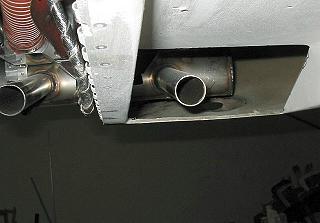
To fix the problem, I had the muffler cut down in depth and re-welded to provide more clearance, and the exhaust pipe angle corrected.

I also decided to cut clearance holes for the corners of the muffler and add blisters with holes to cool the ends where the exhaust pipes enter and the heat would be greatest. Here is the result.

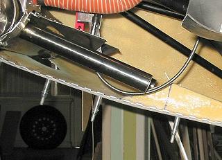
I made a large NACA duct on the side of the cowl to join up with the oil cooler air box inlet. The inlet matches up with the air box with rubber flaps to seal the join. This means that there is no attachment of scat hose or anything else when the cowl is installed.

Cooling air entering the front ducts and the side oil cooler duct needs to escape somewhere. The main exit ducts are ramps with a 1″ lip at the forward side. I made two smaller holes for the oil cooler air exit, again with lips at the front to help the air to clear from inside the cowl.
The next page in Lynn Jarvis’s Sonex project features Paint and polish.
Lynn Jarvis’s Sonex project
| 1. Introduction | 2. Sonex specifications | 3. Building the Sonex |
| 4. The tail and spar | 5. The wing | 6. The aft fuselage | 7. More on the fuselage |
| 8. It all comes together | 9. The canopy | 10. The engine | 11. Electrical | 12. The cowling |
| 13. Paint and polish | 14. Moving | 15. Finishing | 16. First flight | 17. Natfly 2004 |